Chamberlain Liftmaster Wiring Schematic Wiring Diagram
LiftMaster garage door openers are designed to stop if they sense resistance or an ob. Channel: LiftMaster Support Length: 06:30 How to Test the Protector System of Your LiftMaster Garage Door Opener This video demonstrates how to test the Protector System of your LiftMaster garage door opener..

️Chamberlain Garage Door Opener Wiring Diagram Free Download Qstion.co
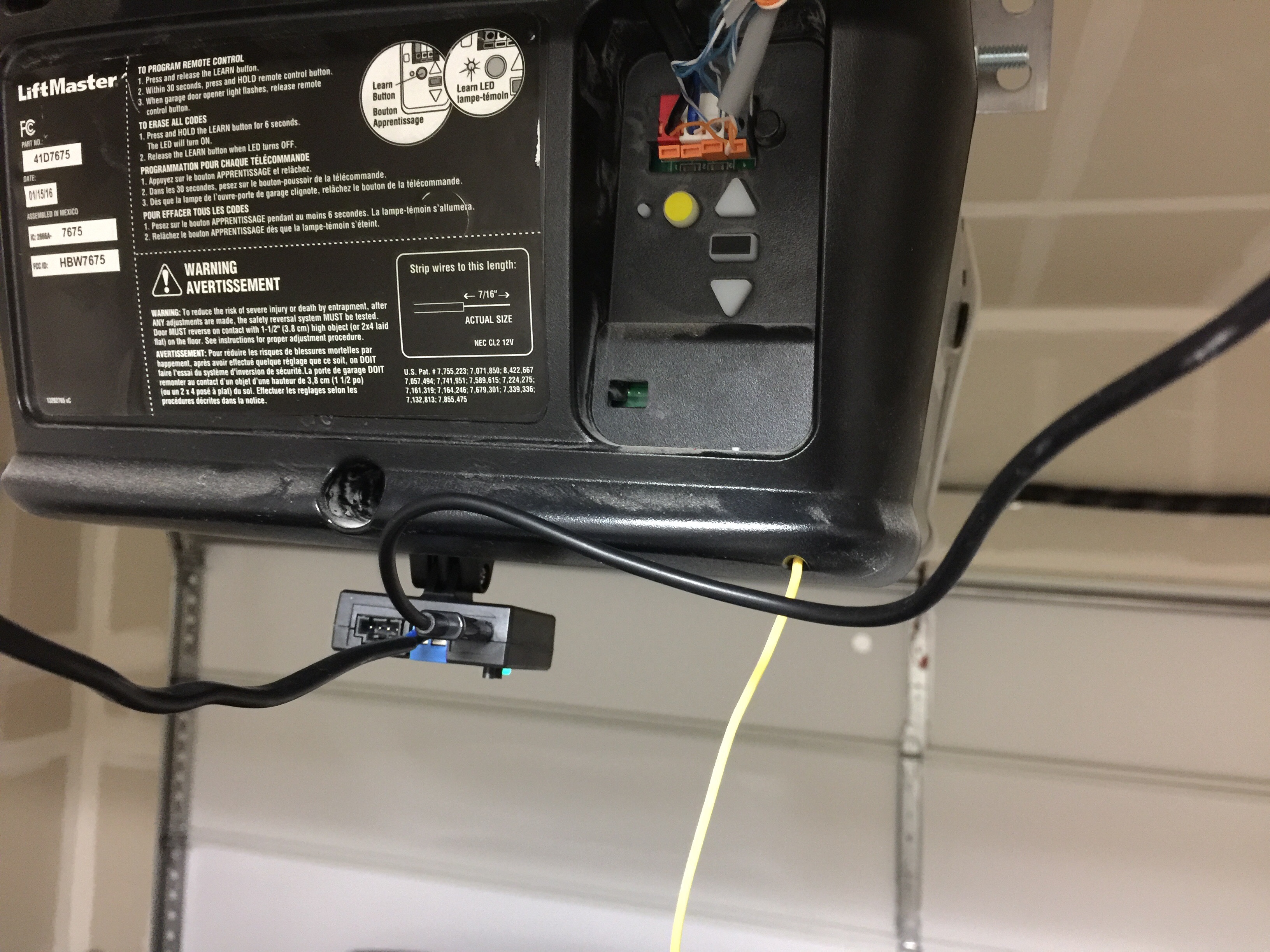
The LiftMaster 7675 is a residential garage door opener that has many features. It can be installed on all types of doors, and it has safety sensors to prevent the door from closing when an object is obstructing it.. (.9 m) 2-conductor wire: 41A5034. Warranty. LIFTMASTER® ONE YEAR LIMITED WARRANTY LIFETIME MOTOR AND BELT* LIMITED WARRANTY.
Garage Sensor Wiring
Title: LIFTMASTER, H, LOGIC 5, COMMERCIAL DOOR OPERATOR, INSTALLATION MANUAL Author: LiftMaster Subject: LIFTMASTER, H, INSTALLATION MANUAL Keywords
How To Fix Chamberlain LiftMaster Error Codes Learn Garage, 51 OFF
When it comes to installing a door opener or gate, one of the most important things to consider is the wiring diagram. Understanding the fundamentals of a Chamberlain Liftmaster Wiring Schematic will prove essential for ensuring safe and reliable long-term operation.

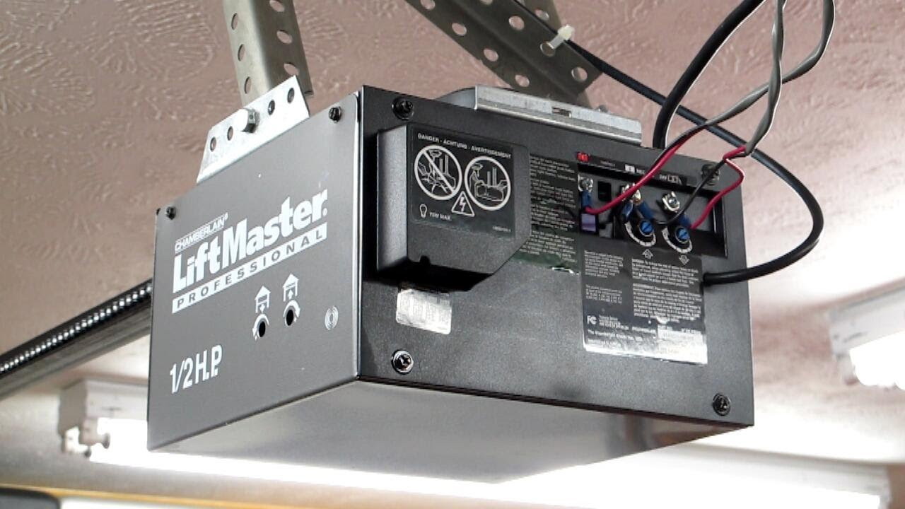
Liftmaster 1/2 Hp Wiring Diagram Adding 850lm
Wiring diagram for garage door opener The sensor for the garage door opener was accidently knocked off. How do I fix it - there are 3 wires and only 2 places to .My wiring for my garage door opener is messed up at the sensors. i am looking for a diagram to show proper wire connections.
Liftmaster Garage Door Opener Wiring Diagram Cadician's Blog
Safety goggles Work gloves Prepare the workspace Before diving into the wiring process, it's crucial to ensure a safe and suitable workspace. Follow these steps to prepare your workspace properly: Disconnect the power: Ensure that you turn off the circuit breaker or unplug the power source to avoid any electrical mishaps.

Wiring Diagram For Liftmaster Garage Door Opener Free Wiring Diagram
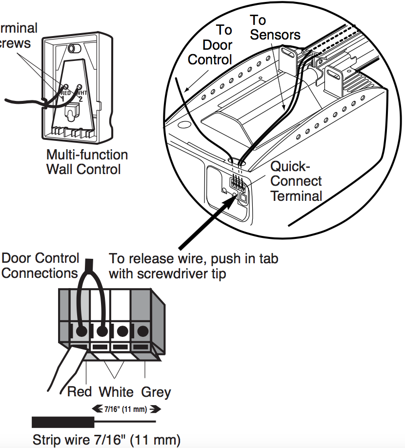
The wiring diagram for Liftmaster sensors typically includes two sensors: one that is placed on the left side of the door and one on the right side. Each sensor has two wires, a black wire and a white wire. The black wires are usually connected to the black terminal on the opener, and the white wires are connected to the gray terminal.

Chamberlain Liftmaster Wiring Schematic Wiring Diagram
CSL24UL Wiring Diagram To reduce the risk of INJURY or DEATH: DISCONNECT power and battery BEFORE installing or servicing operator. Replace ONLY with fuse of same type and rating.
Liftmaster Garage Door Opener Wiring Mary Blog
A wiring diagram is a visual representation of the electrical circuits and components in your LiftMaster garage door opener. It will show you the exact location of each component and how they are wired together. This diagram will also show you what type of wire is used for each connection and where it should be connected.
Liftmaster Wiring Diagram Cadician's Blog
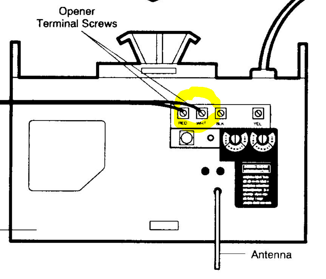
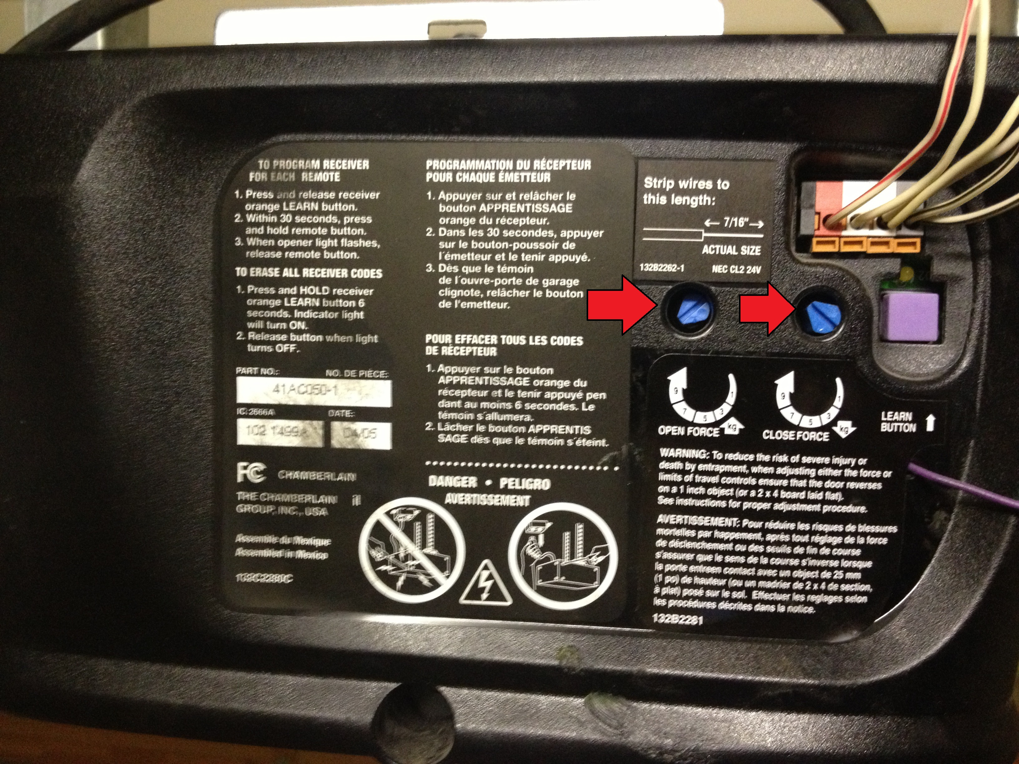
Connect the two wires from the Garadget's blue terminal to the red and white terminals on the garage door opener. Garadget's wires will have to share the terminals with the existing wires connecting the wall button. To insert or release wires from the terminal, push in the tab with screwdriver tip. xNinjas July 19, 2016, 3:37am 2
Liftmaster Garage Door Opener Owner's Manual
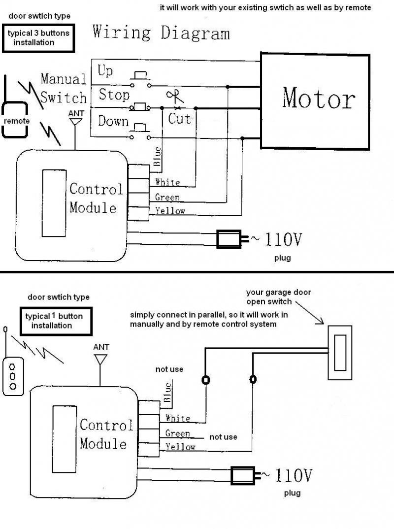
A wiring diagram is a visual representation of the electrical connections and components in a system. This diagram allows installers and technicians to understand the circuitry and ensure proper installation and functioning of the opener.
garage door safety sensor wiring diagram
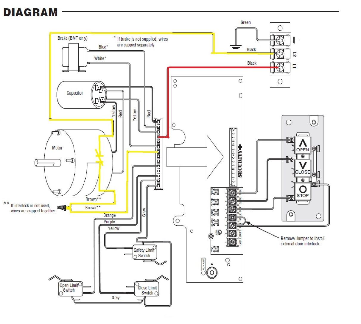
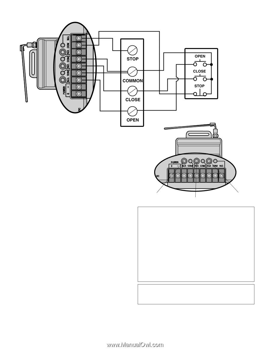
Liftmaster MT5011 door opening system pdf manual download. Also for: Liftmaster bmt5011, Liftmaster mt5025, Liftmaster bmt5025. Sign In Upload. Download Table of Contents Contents. Add to my manuals.. Page 15 WIRING DIAGRAM for BMT 1754 OPEN CLOSE N.C. N.C. AUX.OPEN AUX.CLOSE N.C. N.O. RADIO REC'R TO REVERSE MOTOR DIRECTION INTERCHANGE RED.

Wiring Diagram For Liftmaster Garage Door Opener Free Wiring Diagram
Before 9/3/19:LiftMaster N7 Modification Wiring Diagram LiftMaster N7 Modification Wiring SchematicPost 9/3/19:LiftMaster N7 Modification Wiring Diagram and Schematic B2LiftMaster N7 Modification Wiring Diagram and Schematic Raynor B2 (Different terminals in hazardous area enclosure.)LiftMaster N7 Modification Wiring Diagram and Schematic C2

Chamberlain Liftmaster Garage Door Opener Wiring Diagram Dandk Organizer
move jumper wire to terminal #2 for momentary contact on close br r1 12 or gy gy close-a c r n.o. open l.s. 1 aux. page 17. wiring diagram for bmt5011 • 1754 w w com open p n.c. or close com or n.c. aux.open y p n.o. n.c. aux.close com gy gy w y r3 br r1 radio rec'r r2 to reverse motor direction, interchange red & yellow wires.
Lift Master 850lm Receiver Wiring Schematic Wiring Diagram
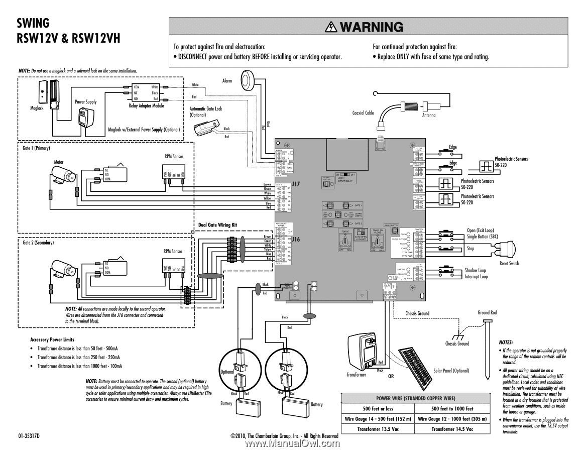
LiftMaster® LA400 Installation/Operation Manual Note: The wire diagram shows the solenoid lock connections incorrectly. The maglock connections are correct. To wire the solenoid lock, use NO and C (normally open and common) terminals on the board instead of NO and NC (normally open and normally closed) terminals on the board. Download Manual

Liftmaster Photo Eye Wiring Diagram
LA500UL Wiring Diagram WIRING DIAGRAM Control Station To reduce the risk of INJURY or DEATH: DISCONNECT power and battery BEFORE installing or servicing operator. Replace ONLY with fuse of same type and rating.